How to Ceck for Continuity on 12 Vold Wiring
Eugene is a qualified control/instrumentation engineer Bsc (Eng) and has worked as a developer of electronics & software for SCADA systems.
What is a Multimeter?
Multimeters are widely used by professionals in several fields including industrial maintenance and testing, research, appliance repair and electrical installation. However a digital multimeter or DMM is also an invaluable test instrument for home and DIY use. The instrument can used for measuring voltage, current and resistance and can check:
- Battery voltages
- Vehicle electrics and electronics
- Continuity of cables and power cords
- Home appliances and electronic devices
- Fuses
Volts, Amps, Ohms - What Does it All Mean?
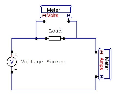
Before we learn how to use a multimeter, we need to become familiar with the quantities we are going to be measuring. The most basic circuit we'll encounter is a voltage source, which could also be connected to a load. The voltage source might be a battery, DC power supply or a mains power supply. There are many types of loads, but typically they could be devices such as bulbs, motors or electronic components called resistors. The circuit can be represented by a diagram called a schematic.
In the circuit below, the voltage source V creates an electrical pressure which forces a current I to flow in a loop around the circuit and through the load R. Ohm's Law tells us that if we divide the voltage V by the resistance R, measured in ohms, it gives us a value for the current I in amps:
Current I = V/R
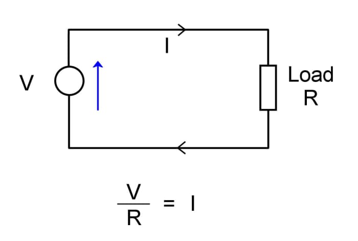
Schematic of a simple circuit.
© Eugene Brennan
Example:
A 12 volt car battery is connected to a load with a resistance of 4 ohms. What is the current?
I = V/R
V = 12 volts
R = 4 ohms
So current I = 12/4 = 3 amps
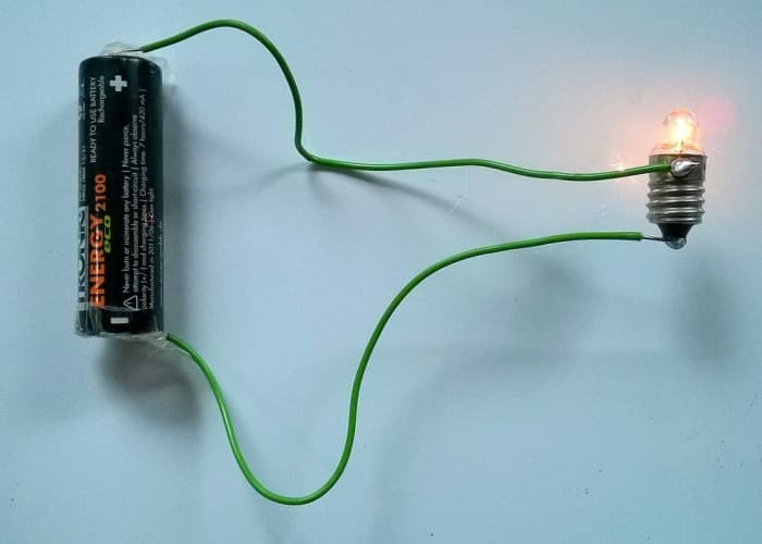
A simple circuit consisting of an AA cell and a bulb. The AA cell is the voltage source that causes current to flow in a loop around the circuit and through the bulb.
© Eugene Brennan
For more detailed information on current, voltage and resistance, AC and DC, take a detour to my other article:
Watts, Amps, Volts, Kilowatt Hours (kWh) and Electrical Appliances - Basic Electricity Explained
What Does a Multimeter Measure?
A basic multimeter allows you to measure the following:
- DC voltage
- DC current
- AC voltage
- AC current (not all basic meters have this function)
- Resistance
- Continuity - indicated by a buzzer or tone
In addition meters may have the following functions:
- Capacitance measurement
- Transistor HFE or DC current gain
- Temperature measurement with an additional probe
- Diode test
- Frequency measurement
The value measured by the instrument is indicated on an LCD display or scale.
Scroll to Continue
Read More From Dengarden
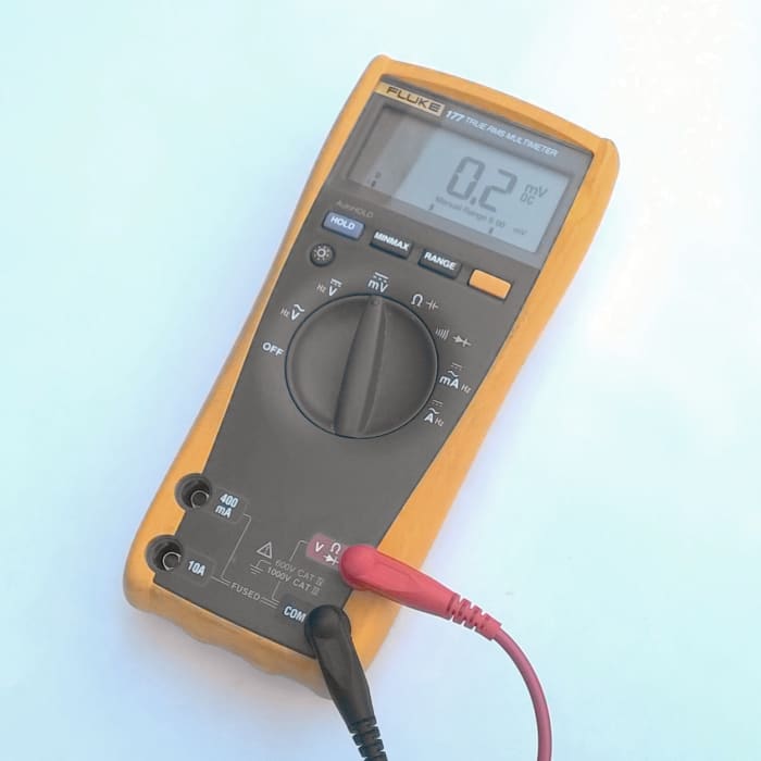
A professional model 177 Fluke multimeter with an accuracy of 0.09 % on DC volts.
© Eugene Brennan
Parts of a Meter
- The Display. This is usually a multidigit, 7 segment LCD display. Some laboratory instruments however have LED displays which are easier to read under certain lighting conditions.
- Rotary Range Selector Dial. This allows you to select the function which you will be using on the meter. On a non-autoranging meter, it also selects the range.
- Connection Ports. These are 4mm diameter female sockets into which 4 mm probe leads are plugged.
- Probes. These have a pointed tip on one end for touching against the point of measurement and a plug on the other end for insertion into a connection socket.
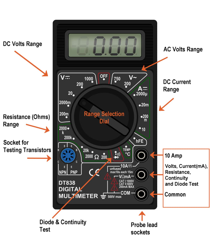
A range selector dial is used to select the function (volts, amps, resistance) and range. Note the symbols used for AC and DC. See graphic further down this article for an explanation.
Original unannotated image public domain via Pixabay.com
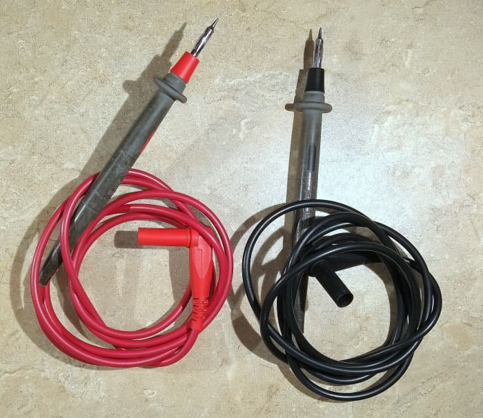
Multimeter probes.
© Eugene Brennan
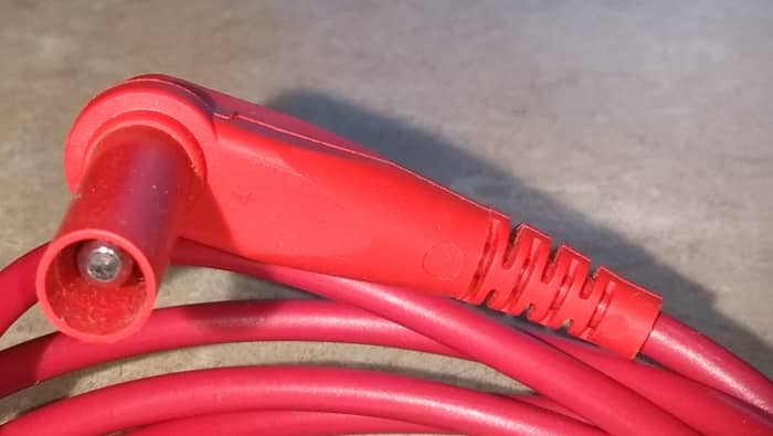
4mm plug on the end of a multimeter probe.
© Eugene Brennan
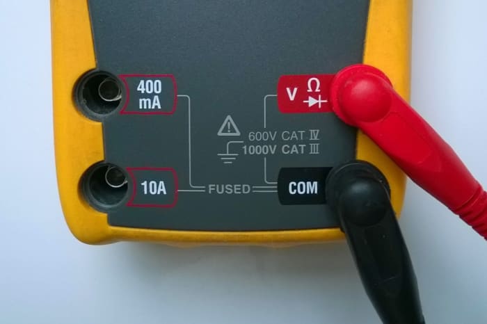
Connection Sockets on a Meter
The arrangement is non-standard and depends on the brand/model of meter, so it's important to understand the function of each socket to avoid damage to the meter:
- Com is the common socket into which the black probe lead is plugged. This is standard on all meters.
- VΩmA marked on a socket indicates that the red probe lead is plugged into it for measuring voltage, resistance or low current ("mA" means "milliamps" for current measurement and the Greek letter Omega "Ω" is the symbol for ohms, the unit of resistance).
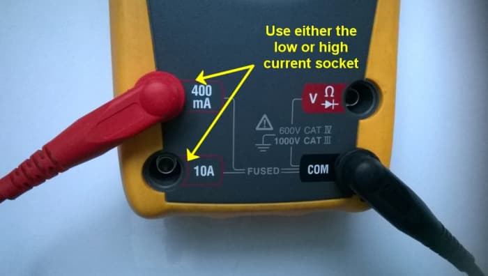
- If there's no mention of "mA" on the socket as explained above, there will be one or more separate sockets for connecting the red probe lead to measure current. These sockets will be marked "A" or "mA" with the max current range (e.g. 10A for high current readings and 400 mA for lower current readings).
How Do I Setup a Multimeter to Measure Volts, Amps or Ohms?
Voltage, current and resistance ranges are usually set by turning a rotary range selection dial. This is set to the quantity being measured, e.g. AC volts, DC volts, Amps(current) or Ohms (resistance).
If the meter is non-autoranging, each function will have several ranges. So for example, the DC volts function range will have 1000V, 200V , 20V, 2V and 200mV ranges. Using the lowest range possible gives more significant figures in the reading.
How to Measure Voltage
- Power off the circuity/wiring under test if there is a danger of shorting out closely spaced adjacent wires, terminals or other points which have differing voltages.
- Plug the black ground probe lead into the COM socket on the meter (see photo below).
- Plug the red positive probe lead into the socket marked V (usually also marked with the Greek letter "omega" Ω and possibly a diode symbol).
- If the meter has has a manual range selection dial, turn this to select AC or DC volts and pick a range to give the required accuracy. So for instance measuring 12 volts on the 20 volt range will give more decimal places than on the 200 volt range.
If the meter is autoranging, turn the dial to the 'V' setting with the symbol for AC or DC (see "What Do the Symbols on the Range Dial Mean?" below). - A multimeter must be connected in parallel in a circuit (see diagram below) in order to measure voltage. So this means the two test probes should be connected in parallel with the voltage source, load or any other two points across which voltage needs to be measured.
- Touch the black probe against the first point of the circuitry/wiring.
- Power up the equipment.
- Touch the other red probe against the second point of test. Ensure you don't bridge the gap between the point being tested and adjacent wiring, terminals or tracks on a PCB.
- Take the reading on the LCD display.
Note: A lead with a 4mm banana plug on one end and a crocodile clip on the other end is very handy. The croc clip can be connected to ground in the circuit, freeing up one of your hands.
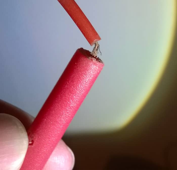
Exposed conductor of test lead
© Eugene Brennan
Connecting Probe Leads to Measure Voltage

Test leads and 4mm sockets on a DMM, setup to measure voltage
© Eugene Brennan
Series and Parallel Connections
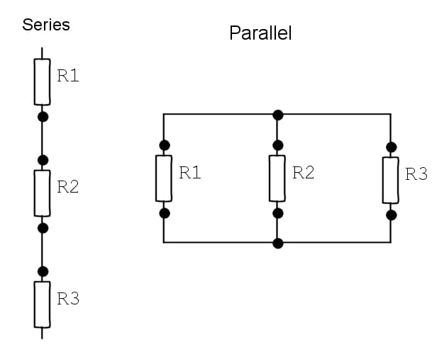
Explaining series and parallel connections (R1, R2 and R3 are resistors)
© Eugene Brennan
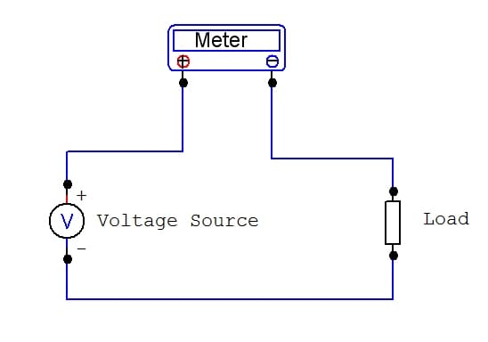
Measuring Voltage - Meter in Parallel With Load or Voltage Source
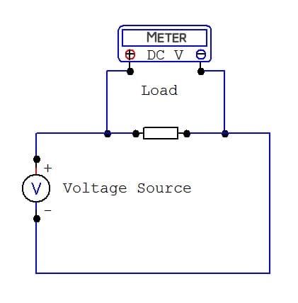
DMM connected in parallel with load to measure voltage across it
© Eugene Brennan
Choosing Test Probes
Most meters come as standard with pointed, needle tip probes. An alternative is crocodile (alligator) probes that have spring loaded clips. These are useful so that one or both probes can be connected to a circuit without holding the probes in place by hand.
Safety First When Measuring Mains Voltages!
- Before using a meter to measure mains voltages, visually inspect it first. Check the meter, probes and accessories are free from damage. Never use test leads with exposed conductors which could be touched inadvertently or a meter with cracks in the casing or exposed metal. Make sure probes are pushed securely into sockets.
- Only use meters and test leads that have a CAT rating suitable for the measuring job. Choose leads with proper insulation, finger guards and shrouded plugs.
Fluke has a safety guide here giving more information on safe multimeter use. - Double check that test leads are plugged into the common and voltage sockets of the DMM (see photo below) and not the current sockets. This is essential to avoid blowing up the meter.
- Set the range dial on the meter to AC volts and the highest voltage range.
- Ideally use test leads with shrouded crocodile clips on the ends, power off the circuit, connect the leads and power up again so you don't have to hold leads. TV repair technicians used to have a saying that the safest place to keep one of your hands is in your pocket when making measurements. When holding a probe in each hand, there's always the danger of making contact with neutral or ground with one hand and hot (live) with the other if the probe or leads are damaged, resulting in a shock across the heart, a potentially lethal scenario. Alternatively the negative probe lead can be connected to neutral using a crocodile connector so that measurements can be taken with one hand using the positive needle probe.
- If you have to measure voltage at a socket outlet, turn off power before inserting probe tips. If this isn't possible, always insert the probe tip into the neutral terminal of the outlet first and then insert the other probe into the live (hot) terminal. If you insert the probe tip into the hot first and inadvertently touch the tip of the other probe, or it makes contact with a metal surface, you can get a shock or potentially be electrocuted.
Meter and Measurement Safety Categories
Ideally buy and use a meter with a least CAT III or preferably CAT IV protection for testing mains voltages. This type of meter will incorporate high rupturing capacity (HRC) fuses and other internal safety components that offer the highest level of protection against overloads and transients on the line being tested. A meter with less protection can potentially blow up causing injury if it is connected incorrectly, or a transient voltage generates an internal arc.
Autoranging Meters
Autoranging meters detect the magnitude of the voltage and select the range automatically to give the most amount of significant digits on the display. You must however set the mode to resistance, volts or current and also connect the probe leads to the proper sockets when measuring current.
What Do the Symbols on the Range Dial Mean?
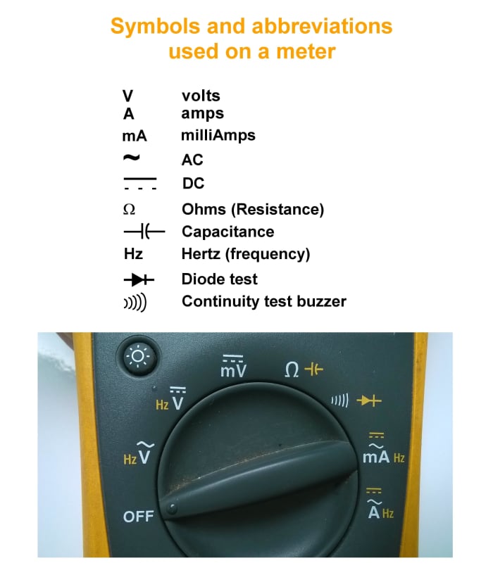
Symbols used on an autoranging DMM
© Eugene Brennan
Identifying Live or Hot Wires
This Fluke "VoltAlert™" non-contact voltage detector from Amazon is a standard tool in any electricians tool kit, but useful for homeowners also. I use one of these for identifying which conductor is live whenever I'm doing any home maintenance. Unlike a neon screwdriver tester (phase tester), you can use one of these in situations when live parts/wires are shrouded or covered with insulation and you can't make contact with wires. It also comes in useful for checking whether there's a break in a power flex and where the break occurs.
Note: It's always a good idea to use a neon tester to double check that power is definitely off when doing any electrical maintenance.
How to Measure Current
- Turn off the power in the circuit being measured.
- Connect the probe leads as shown in the photo below. Plug the black ground probe lead into the COM socket.
- Plug the red positive probe lead either into the mA socket or the high current socket which is usually marked 10A (some meters have a 20 A socket instead of 10A). The mA socket is often marked with the maximum current and if you estimate that the current will be greater than this value, you must use the 10 A socket, otherwise you will end up blowing a fuse in the meter. On some meters, there is no additional socket for measuring current and the same socket is used as for measuring voltage (usually marked VΩmA).
- A multimeter must be inserted in series in a circuit in order to measure current. See the diagram below.
- Turn the dial on the meter to the highest current range (or the 10A range if the probe is in the 10A socket). If the meter is autoranging, set it to the "A" or mA setting. (See the photo above for an explanation of symbols used).
- Turn on the power.
- If the range is too high, you can switch to a lower range to get a more accurate reading.
- Remember to return the positive probe to the V socket when finished measuring current. The meter is practically a short circuit when the lead is in the mA or 10 A socket. If you forget and connect the meter to a voltage source when the lead is in this position, you may end up blowing a fuse at best or blowing up the meter at worst! (On some meters the 10A range is un-fused).
Connecting Probe Leads to Measure Current
Test leads and sockets on a DMM, setup to measure current
© Eugene Brennan
Measuring Current - Meter in Series
DMM connected in series with load to measure current flowing through it
© Eugene Brennan
What Multimeter Should I Buy? Recommended Products From Amazon
Fluke, a leading US manufacturer of digital instrumentation, promotes the Fluke 113 model for general purpose use in the home or for car maintenance. This is an excellent meter and can measure AC and DC volts, resistance, check continuity and diodes. The meter is auto-ranging, so ranges don't have to be set. It is also a true-RMS meter. It doesn't measure current, so If you need to measure AC and DC current, the Fluke 115 has this added facility.
An alternative is the Fluke 177 model which is a high accuracy instrument (the specification is 0.09% accuracy on DC volts). I use this model for more accurate testing and professional use and it can measure AC and DC voltage and current, resistance, frequency, capacitance, continuity and diode test. It can also indicate max and min values on each range.
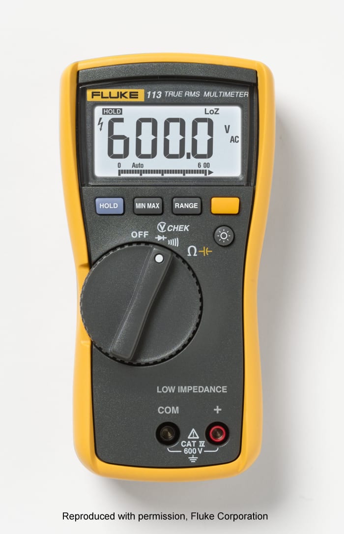
Fluke 113 general purpose true RMS digital multimeter.
Image reproduced with permission from Fluke Corporation
Fluke 177 Multimeter with Auto-Ranging Facility
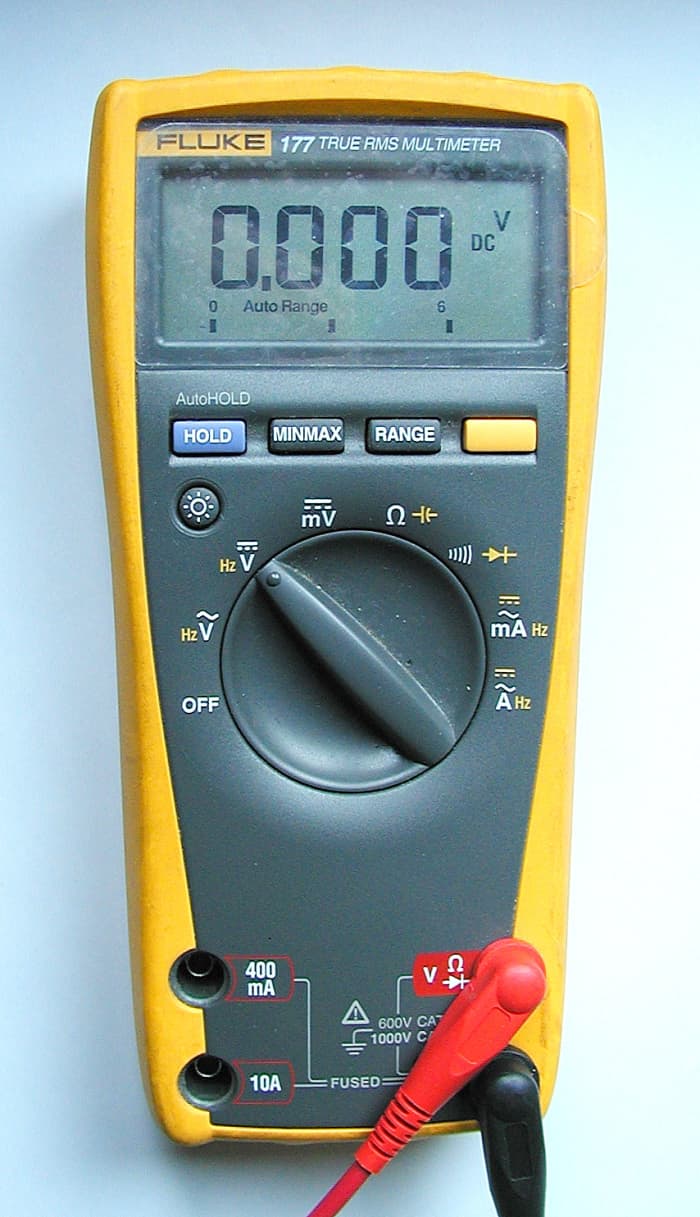
This autoranging multimeter from Fluke, a leading manufacturer of electronic test equipment, has an accuracy of 0.09% on DC ranges. It also has CAT IV protection to 600volts
© Eugene Brennan
Measuring Large Currents with a Clamp Meter (Tong Tester)
On most multimeters, the highest current range is 10 or 20 amps. It would be impractical to feed very high currents through a meter because normal 4 mm sockets and test leads wouldn't be capable of carrying high currents without overheating. Instead, clamp meters are used for these measurements.
Clamp meters (as the name suggests), also known as tong testers, have a spring loaded clamp like a giant clothes peg which clamps around a current carrying cable. The advantage of this is that a circuit doesn't have to broken to insert a meter in series, and power needn't be turned off as is the case when measuring current on a standard DMM. Clamp meters use either an integrated current transformer or hall effect sensor to measure the magnetic field produced by a flowing current. The meter can be a self contained instrument with an LCD which displays current, or alternatively the device can output a voltage signal via probe leads and 4mm "banana" plugs to a standard DMM. The voltage is proportional to the measured signal, typically 1mv represents 1 amp.
Clamp meters can measure hundreds or thousands of amps.
To use a current clamp, you simply clamp over a single cable. In the case of a power cord or multicore cable, you need to isolate one of the cores. If two cores carrying the same current but in opposite directions are enclosed within the jaws (which would be the situation if you clamp over a power cord), the magnetic fields due to the current flow would cancel out and the reading would be zero.
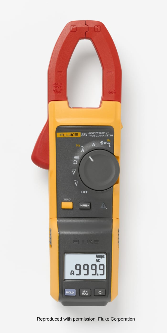
Fluke 381 True RMS AC/DC clamp meter
Image reproduced with permission from Fluke Corporation
How to Measure Resistance
- If the component is on a circuit board or in an appliance, turn off the power
- Disconnect one end of the component if it's in a circuit. This may involve pulling off spade leads or desoldering. This is important as there may be other resistors or other components having resistance, in parallel with the component being measured.
- Connect the probes as shown in the photo below.
- Turn the dial to the lowest Ohm or Ω range. This is likely to be the 200 ohm range or similar.
- Place a probe tip at each end of the component being measured.
- If the display indicates "1", this means that resistance is greater than can be displayed on the range setting you have selected, so you must turn the dial to the next highest range. Repeat this until a value is displayed on the LCD.
Connecting Probe Leads to Measure Resistance

Leads setup to measure resistance
© Eugene Brennan
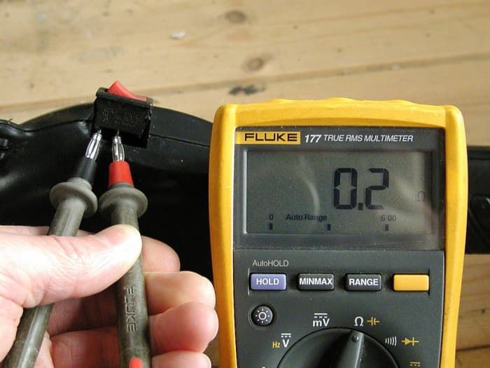
Check resistance across switch contacts
© Eugene Brennan
How to Check Continuity and Fuses
A multimeter is useful for checking breaks in flexes of appliances, blown filaments in bulbs and blown fuses, and tracing paths/tracks on PCBs
- Turn the selecting dial on the meter to the continuity range. This is often indicated by a symbol which looks like a series of arcs of a circle (See the photo showing symbols used on meters above).
- Connect the probe leads to the meter as shown in the photo below.
- If a conductor on a circuit board/ a wire in an appliance needs to be checked, make sure the device is powered down.
- Place the tip of a probe at each end of the conductor or fuse which needs to be checked.
- If resistance is less than about 30 ohms, the meter will indicate this by by a beep tone or buzzing sound. The resistance is usually indicated on the display also. If there is break in continuity in the device being tested, an overload indication, usually the digit "1", will be displayed on the meter.
Connecting Probe Leads to Check Diodes or Continuity
Leads setup to check diodes or continuity
© Eugene Brennan
How to Check Diodes
A multimeter can be used to check whether a diode is short circuited or open circuited. A diode is an electronic one way valve or check valve, which only conducts in one direction. A multimeter when connected to a working diode indicates the voltage across the component.
- Turn the dial of the meter to the diode test setting, which is indicated by a triangle with a bar at the end (see the photo showing symbols used on meters above).
- Connect the probes as shown above.
- Touch the tip of the negative probe to one end of the diode, and the tip of the positive probe to the other end.
- When the black probe is in contact with the cathode of the diode (usually indicated by a bar marked on the component) and the red probe makes contact with the anode, the diode conducts, and the meter indicates the voltage. This should be about 0.6 volts for a silicon diode and about 0.2 volts for a Schottky diode. When the probes are reversed, the meter should indicate a "1" because the diode is open circuit and non-conducting.
- If the meter reads "1" when the probes are placed either way, the diode is likely to be faulty and open circuit. If the meter indicates a value close to zero, the diode is shorted circuited.
- If a component is in circuit, resistances in parallel will affect the reading and the meter may not indicate "1" but a value somewhat less.
How to Measure Wattage and the Power Consumption of an Appliance With a Multimeter
Watts = Volts x Current
So to measure the power in watts of a load/appliance, both the voltage across the load and the current passing through it must be measured. If you have two DMMs, you can measure the voltage and current simultaneously. Alternatively measure the voltage first, and then disconnect the load so that the DMM can be inserted in series to measure current. When any quantity is measured, the measuring device has an influence on the measurement. So the resistance of the meter will reduce current slightly, and give a lower reading than the actual value with the meter not connected.
Three ways to measure current drawn by an electrical appliance:
- The safest way to measure the power consumption of an appliance powered from the mains is to use a power adapter. These devices plug into a socket and the appliance is then plugged into the adapter which displays information on an LCD. Typical parameters displayed are voltage, current, power, kwh, cost and how long the appliance was turned on (useful for fridges, freezers and air conditioners which cut in and out). You can read more about these gadget in my article here:
Checking Power Consumption of Appliances With an Energy Monitoring Adapter - An alternative way of safely measuring current drawn by an electrical appliance is to make up a test lead using a short piece of power cord with a trailing socket on one end and a mains plug on the other. The inner neutral core of the power cord could be freed and separated from the outer sheath, and current measured with a clamp meter or probe (Don't remove the insulation!)
Only make connections and adjust range on the meter with the power off!
Measuring watts = volts x amps. One meter measures voltage across the load. The other meter measures current flowing through it.
© Eugene Brennan
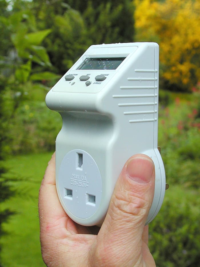
Power adapter. (Also known as an energy monitor/power tracker)
© Eugene Brennan
How to Check Peak Voltages - Using a DVA Adapter
Some meters have a button which sets the meter to read max and min RMS voltages and/or peak voltages (of the waveform). An alternative is to use a DVA or Direct Voltage Adapter. Some components such as CDI (Capacitor Discharge Ignition) modules on vehicles, boats and small engines produce pulses which vary in frequency and can be short duration. A DVA adapter will sample and hold the peak value of the waveform and output it as a DC voltage so the component can be checked to see whether it's producing the correct voltage level. A DVA adapter typically has two probe leads as input for measuring voltage and either two output leads with banana plugs or a connector with fixed plugs attached for plugging into a meter with standard spaced sockets. The meter is set to a high DC voltage range (e.g. 1000 volts DC) and the adapter typically outputs 1 volt DC per 1 volt AC input.
Important information for anyone using a DVA to check ignition circuits!
In this application, the adapter is used for measuring the primary voltage of a stator/ignition coil, not the secondary voltage, which could be about 10,000 volts or more.
Fluke also manufacture meters that can capture the peak level of short transients e.g. - The Fluke-87-5, Fluke-287 and Fluke-289 models.
True RMS Multimeters
The voltage supply to your home is AC, and voltage and current vary in polarity over time. The waveform is sinusoidal as in the diagram below and the change of direction of current is known as the frequency and measured in Hertz (Hz). This frequency can be 50 or 60 Hz, depending on which country you live in. The RMS voltage of an AC waveform is the effective voltage and similar to the average voltage. If the peak voltage is Vpeak, then the RMS voltage for a sinusoidal voltage is Vpeak / √2 (approx 0.707 times the peak voltage). The power in a circuit is the RMS voltage multiplied by the RMS current flowing in a load. The voltage normally printed on appliances is the RMS voltage even though this is not usually stated.
A basic multimeter will indicate RMS voltages for sinusoidal voltage waveforms. The supply to our homes is sinusoidal so this isn't a problem. However if a voltage is non sinusoidal, e.g. a square or triangular wave, then the meter will not indicate the true RMS voltage. True RMS meters however are designed to correctly indicate RMS values for all shaped waveforms.
The AC Supply Feeding Our Homes is a Sine Wave
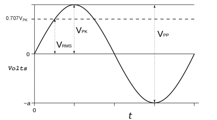
RMS and peak voltages of an AC sine waveform. Vpp is the peak to peak voltage
AlanM1, public domain image via Wikimedia Commons
Measuring Voltages Remotely and Logging Readings
If you need to measure voltages and log them over time, you can use a datalogging multimeter. A product such as the Fluke 289 True-RMS datalogging multimeter can record 15,000 readings. Another feature of this meter is that it can be setup with a wireless connector to communicate with an Android mobile device, allowing readings to be viewed remotely, while the meter is located elsewhere.
FAQs About Multimeters
How Do You Check Voltage With a Multimeter?
Plug the black probe into COM and the red probe into the socket marked VΩ. Set the range to DC or AC volts and touch the probe tips to the two points between which voltage needs to be measured.
How Do You Check if a Wire is Live With a Multimeter?
For this it's best to stay safe and use a non-contact volt tester or phase tester screwdriver. These will indicate if voltage is e.g > 100 volts. A multimeter can only measure the voltage between live and neutral or live and earth if these conductors/terminals are accessible, which may not always be the case.
How Do You Check Voltage Drop With a Multimeter?
Voltage drop occurs across a resistance or along a power cable. So follow the same procedure as for measuring voltage and measure voltage at the two points of interest and subtract one from the other to measure voltage drop.
Why is Voltage Drop Important?
If voltage drop is excessive, appliances may not work properly. Cable should be sized adequately to minimise voltage drop for the current it needs to carry and the distance over which current travels.
References
Digital Multimeter Troubleshooting & Solutions. Fluke. (n.d.). https://www.fluke.com/en-us/learn/blog/digital-multimeters
Digital multimeter: What is the accuracy, range and resolution? (2021, May 9). Fluke. https://www.fluke.com/en-ie/learn/blog/digital-multimeters/accuracy-precision
This article is accurate and true to the best of the author's knowledge. Content is for informational or entertainment purposes only and does not substitute for personal counsel or professional advice in business, financial, legal, or technical matters.
Questions & Answers
Question: To be clear, am I correct in my interpretation that if I want to check that there is 230v in my electrical connections in a light fitting that is glowing dimly, I need the lamp in first to complete the circuit, then I check either end of the fitting placing the meter in parallel? Conversely, if I were to use the meter in lieu of the lamp, then this would be in series and the reading would be false or the meter would simply not work?
Answer: If the fitting is wired correctly, it doesn't matter much if the lamp is in place or not as regards measuring the voltage. Yes, you do connect a meter in parallel with a load (i.e. the lamp in your case) to measure voltage. But because a lamp doesn't take much current, it doesn't drop voltage significantly. Now if the load was high powered e.g. a heater, the voltage would drop a few volts. The open circuit voltage of a voltage source is always higher than the output voltage on load because a real voltage source always has internal resistance, plus the connecting wires have resistance also. So if the connecting wires are long or cross-sectional area is small, the voltage drop can be considerable if the wiring is sized inappropriately. If you connect the meter to the fitting without the lamp, it's in parallel with the output terminals on the fitting and because it's set to "volts", no current flows through it (well actually just a little, but microamps because it has such a high resistance). If the meter was set to "amps" it would be like a short circuit and effectively in series with the supply and a fuse would blow. Maybe the concept of parallel and series is a bit confusing. Just remember that when the meter is set to volts, it measures the voltage between two points and when set to amps, it measures the current flowing between the two points.
Question: How do I test and identify faults of three phase system of both control circuit and power circuit for motors?
Answer: Have a look at this document which may help:
https://www.schneider-electric.hu/documents/automa...
© 2012 Eugene Brennan
Collins on October 22, 2019:
Useful
Eugene Brennan (author) from Ireland on April 03, 2019:
A meter has a very high impedance and sensitivity to voltage. Even though the black isn't connected to anything, there is capacitance between the metal probe tip and wire of the black lead and ground. So a minute current can actually flow backwards and forwards through the air as this tiny capacitor charges and discharges as the AC continually changes direction, If you've ever put your hand on a plasma ball, a discharge flows through the ball to the glass at the point where your hand touches it. This is pretty much for the same reason. Look up capacitors on Wikipedia for more info.
Jay Mengel on April 03, 2019:
I am replacing a ceiling fan. In checking the voltages i find i get a reading of 9 - 10 volts when I connect only the red lead of my test meter to the hot wire. The black is not connected to anything. Is there an explanation? If touch the black lead to ground or the common wires I get 120 volts (+/- a couple)
Eugene Brennan (author) from Ireland on December 09, 2018:
Thanks Michael for the feedback!
If you have any questions about multimeters or electricity, just ask.
Michael Kingston on December 08, 2018:
Having just enrolled on a auto electrical course at Cardiff and the Vale College, Cardiff and no nothing about vehicle electrics. I find your article about multimeters fascinating. Thank you!
Eugene Brennan (author) from Ireland on November 30, 2018:
Hi Mark, it possibly could. Sometimes adapters aren't regulated and 12 volts output means the voltage it gives on full load, but this can rise when off load. A regulated adapter gives a constant voltage, independent of load. If it's an AC adapter, it's probably just a transformer, without any regulating electronics. 17.4 volts sounds very high though for a 12 volt adapter off load, a volt or two would be normal.
Does the microscope definitely require AC, rather than DC? Without being able to load the adapter with a current equivalent to what the microscope takes and see if voltage falls, I can't say whether or not it would cause damage.
Mark on November 30, 2018:
I just bought a 12v (written on on it) AC adapter. I measured the voltage at the tip of it with a Fluke meter. I am reading 17.4v, is this normal? My device (a LED illuminated microscope) requires 12v. Will I damage the LED bulb if I use this AC adapter?
Eugene Brennan (author) from Ireland on October 20, 2018:
Only if they're connected to a high voltage source. Above about 50 V, a voltage source will begin to produce a sensation. However the intensity and actual threshold level depends on several factors such as location on the body of the point of contact, nature of the skin e.g. smooth or calloused, whether skin is dry or moist etc. An ohmmeter or multimeter set to the ohms range, outputs a voltage and uses this to feed a current through a connected resistance in order to calculate its value (R = V / I). However this voltage is relatively low. A Megger type insulation tester as used for checking insulation quality in electrical installations however, generates much higher voltages which will shock.
Mike gordon on October 20, 2018:
Can the probes shock me if I touch them
Eugene Brennan (author) from Ireland on July 23, 2018:
Hi Pranjal. Yes you can measure AC current if the meter has an AC current range. The procedure is the same as for measuring DC current described above. If measuring mains currents, precautions must be taken, including but not limited to the following:
1 Check that probes are not damaged with any exposed conductors
2 Set the meter to the appropriate range and make connections with power turned off
3 If you estimate that the current will be higher than the maximum range, use the high current setting and use the high current (e.g. 10A or 20A) socket
4 If you don't know the current, but think it may be greater than the value of the highest current range, you will need to use a clamp meter. The high current range may not be fused.
5 Use a meter with a CAT rating to suit the conditions of measurement
pranjal on July 23, 2018:
sir can we check the ac current using digital multimeter and without clamp meter if yes then how?
g.chick. on July 04, 2018:
very, very useful information; even for a 71 year old novice like myself. Thankyou for all the time you must have invested in this posting.
Eugene Brennan (author) from Ireland on June 13, 2018:
I'm not an electrician, but I presume a "Megger" type instrument would be required for testing insulation plus another for testing earth loop impedance and a third for testing RCDs. Alternatively a multifunction tester to all tests could be used. A multimeter would be of limited use.
MGREEN201 on June 13, 2018:
Thanks Eugene. I have some of them already. Can you suggest any decent journal articles or published papers .. I realy need to use excessive literature review for my work and would appreciate any suggested sources
MGREEN201 on June 13, 2018:
I had an electrician who used a multi meter to carry out an EICR ( PERIODIC TESTING ) USING A MULTI METER. I WAS SUPRISED AS I DIDN'T THINK IT WAS POSSIBLE HE ASSURED ME IT WAS. NUT QUESTION IS .IS IT POSSIBLE TO DO A FULL EICR ( PERIODIC TEST ) USING A MULTI METER.i know for a fact that he couldn't get a tripping time for the rcd
Dinesh on May 30, 2018:
Nice information thanks
Fredrick Mtonga on May 25, 2018:
thank you very much, the notes are brief I have learned a lot. ..
Eugene Brennan (author) from Ireland on May 09, 2018:
ABF, can you explain this a bit clearer?
ABF on May 09, 2018:
when we measure the current between two source is not applicable. why?
mintesenot debebe on April 22, 2018:
I have no words that's nice and brilliant note I wanna say thank you.
bob on March 24, 2018:
very needed -thanks
Eugene Brennan (author) from Ireland on February 04, 2018:
Important! - For anyone using a DVA adapter mentioned below. These adapters are for measuring the primary voltage of a stator/ignition coil, not the secondary voltage, which could be about 10,000 volts.
Fluke also manufacture meters that can capture the peak level of short transients e.g. - The Fluke-87-5, Fluke-287 and Fluke-289
Eugene Brennan (author) from Ireland on November 20, 2017:
Hi Jabba,
The meter is practically a short circuit when the the leads are connected to measure current. If you connect it to a voltage source, it will blow the fuse in the meter. The high current range (10A/20A range) may not be fused on a cheap meter, so the meter will likely be destroyed if the voltage source can potentially supply a large current (the mains or a battery).
Does this answer your question?
jabba on November 20, 2017:
What is the consequence when testing (current) A and the probes are connected to (voltage) V?
Loves chowri on October 10, 2017:
When you say the probe is in open air, are you holding it, or is it resting on a surface?....
Tsegazeab on August 31, 2017:
How we measure the laptop voltage regulator
Eugene Brennan (author) from Ireland on August 03, 2017:
Hi J,
First check the meter reads 0 volts with the probes touched together to confirm there isn't a fault causing it to display an offset voltage.
When you say the probe is in open air, are you holding it, or is it resting on a surface?
A digital multimeter has a high impedance, typically 10 megaohms. When one probe is contacting a 220 volts supply and the other end is in free air, you effectively have a potential divider circuit. A potential divider (Google it for more details) consists of a number of resistors connected in series. When the divider is connected to a voltage supply, a reduced voltage is available at the junction between the resistors (an example is the volume control on a radio). In the most simplest of examples, two resistors of equal value will give half the input voltage at the junction. In your case, the meter forms one part of the potential divider. The other part consists of the resistance from probe through the air to ground (practically infinite), the resistance from the probe through your hand to ground (could be hundreds of megaohms if there is high humidity) and the reactance of the probe to ground (due to capacitance). The latter three are in parallel.
J. Karthikeyan on August 03, 2017:
Digital multimeter two probes. One probe places in phase 230VAC, another probe placed in open air. But meter reading shows 30V. Meter reading is correct? Pls explain.
Don on April 08, 2017:
Verry informative information was a bit stale now remember many thanks kind regards Don
Rochy/Scientist Sandy. on April 01, 2017:
Thank you very much for such helpful information, I'm passionate with electronics and inventing some cool devices, and my aim is to make free energy/electricity, so my problem is that I don't know how do we determine voltage a diode can handle like 1N4008 or 1N540 and Voltage regulator and transistor, my question is how do we determine their voltage rating because some of them are not even written or they're faded and where and in which circumstances do we use suppression capacitor, I'd like it if u poke me on my email when u get chance to answer my question and where to follow my answer Makhokha93@gmail.com thank you for your knowledge.
Eugene Brennan (author) from Ireland on January 25, 2017:
You can use a potential divider circuit to measure high voltages with a low voltage range meter. In fact this is how the internal circuitry in a meter reduces voltage for the various ranges. However the effort required isn't really worth it. You would also have to build everything into a box so that there are no wires/terminals/components exposed which could cause shock. You can buy a multimeter for about $10 from Dealextreme or other similar gadget suppliers which will measure voltage, current and resistance.
TW on January 25, 2017:
How to use a low range voltmeter for high voltages
Eugene Brennan (author) from Ireland on October 16, 2016:
Hi Pascal,
This won't damage the meter (assuming the voltage is less than the rating at the input sockets, typically 600 volts)
An AC voltage is in effect DC for each half of a cycle, so DC is being applied to the inputs anyway.
Remember when you are making a measurement with a meter to set the range first before you connect the probes to the voltage under test.
When measuring current, a meter usually has two current sockets. The lower current socket is usually fused, but the higher current socket may or may not be fused. If you estimate the current being measured will be higher than the value indicated on the lower current socket, connect the probe to the higher current socket, otherwise you'll nd up blowing a fuse.
Hope this helps!
pascal on October 16, 2016:
hi I have a question suppose that I want to measure a DC voltage and I mistaken I point the rotary to AC . what will I do?
Eugene Brennan (author) from Ireland on November 08, 2014:
Hi "lost",
by test leads being damaged, I mean any insulation scuffed, peeled back or cut to the extent that the inner copper cores are exposed and liable to be touched. Also insulation can crack, and leads pull out from the probe or plug end of the test lead, again exposing the conductor. I think I have a damaged set of leads, so I'll upload a photo.
I'll add explanations with graphics of serial and parallel connections. Let me know if anything else needs explaining.
lost on November 08, 2014:
Very Good info , can you explain what some of the things are for people like myself that are Very Very unfamiliar with the terminology ? In the safety first alone I was lost on leads not being damaged , (maybe a picture glossary of lingo) or what a series or parallel is etc. love this hub ,just from my lack of certain words or terms and their meaning I was lost from the start. Thank You
douglasalationever.blogspot.com
Source: https://dengarden.com/home-improvement/Using-a-Multimeter
0 Response to "How to Ceck for Continuity on 12 Vold Wiring"
Post a Comment